Orifice plate sizing calculator

orifice size and flow calculations

online since 2005

Description

This calculator performs the flow rate calculation from the measured pressure drop caused by the orifice plate inserted in the pipeline.

The calculator is suitable for liquids and perfect gases, a subsonic flow of single phase fluid.

Registration and subscription

Select a subscription plan and enable the full service:

  • Switch between metric and imperial units in one click
  • Export calculation results in Word .docx or Excel .xlsx format
  • Preview results on one place and copy/paste it in your favorite text editor
  • Send results back to your email
  • Support the future of this project

And even more... Subscribed users have access to the full set of 19 calculators available as Java™ Web start application or download Windows™ 64bit application.

Subscribe

Full year subscription

Monthly cost
$250/month

Full year subscription $29.95/year

Action
Calculation setup
Pressures
Flow rates and velocities
Orifice dimensions and coefficients
Fluid properties

Exclusive calculator

On exclusive calculator page you can use the online calculator without interference from advertisements, additional text, links and other content that is not required for the calculations themselves. A pure experience of using a calculator as with a desktop application.

An exclusive version of the calculator is available to registered users. Choose the right subscription duration and start using the exclusive service.

Exclusive

Description

p1 - pressure on the inlet
Absolute pressure in front of the orifice
p2 - pressure on the outlet
Absolute pressure after the orifice
Δp - pressure drop
Pressure difference between pipe start and pipe end
Δω - pressure loss
That can't be recovered after the orifice
D1 - diameter of tube
Internal pipe diameter
D2 - orifice size
Diameter of orifice
e - expansion factor
Coefficient used for compressible flow calculation
C - coefficient of discharge
Coefficient used for orifice plate based on ISO 5167
ReD - upstream Reynolds number
Reynolds number calculated in front of the orifice
K - resistance coefficient
That you can use in pipeline calculation, as orifice is creating local pressure losses in the pipeline
q1 - volumetric flow rate
Fluid flow rate in terms of units of volume per unit of time on the inlet conditions
q - standard flow
Flow rate at standard conditions. Used only if the selected fluid is gas.
ṁ - mass flow rate
Fluid flow rate in terms of units of mass per unit of time
V1 - upstream velocity
Flow velocity in front of the orifice where flow diameter is D1
T1 - upstream temperature
Fluid temperature for gas density calculation based on the ideal gas state equation
ρ1 - upstream density
Fluid density in the front of orifice in terms of mass per unit of volume
R - gas constant
Gas constant in terms of energy per unit of mass and temperature, for gas density calculation using ideal gas state equation
κ - isentropic coefficient
Specific heat ratio
ν - kinematic viscosity
Result of fluid particles colliding to each other and moving at different velocities in terms of area per square unit of time
μ - dynamic viscosity
Result of fluid particles colliding to each other and moving at different velocities in terms of mass per square unit of distance and time

Sizing calculation setup

Select orifice type based on the measuring taps placement
Corner taps
When measuring taps are placed in the orifice corners
Flange taps
When measuring taps are placed in the orifice flanges
D - D/2
When measuring taps are placed in front and after the orifice on given distance
Select value to input. You should enter selected one. The other one will be calculated
p2
pressure downstream from the orifice
Δp
measured pressure difference in front and after the orifice
Select value to input. You should enter selected one. The other one will be calculated
ν
kinematic viscosity
μ
dynamic viscosity
Select value to input. Available only if gas is selected. You should enter selected one. The other one will be calculated
T1
upstream temperature.
ρ1
upstream density.
Select fluid type
Gas
for compressible flow where ideal gas state equation is applicable
Liquid
for incompressible flow of liquids
Application of ISO 5167 constraints
ISO constraints
Deselect if you don't want to check if the orifice and the flow conditions are within the limits of the ISO standard.

Why should you use this calculator?

Use this calculator to quickly calculate the actual flow rate through the orifice plate flow meter with only a few inputs. This calculator performs the flow rate calculation from the measured pressure drop caused by the orifice plate inserted in the pipeline.

When is this calculator relevant?

The calculator is suitable for liquids and perfect gases, a subsonic flow of single phase fluid. It is not applicable for pulsating flow. The pipeline should be circular. The calculator is not applicable for rectangular ducts.

When is this calculator not relevant?

This calculator is not suitable for multiphase fluids, like a flow of liquids that contain solid particles or flow of liquids that contain undissolved gases. Also, it is not suitable for gases that are not ideal, i.e., gases that don't relate to the ideal gas law.

What has to be understood to perform the calculation?

To calculate flow rate, you have to enter the orifice plate throat diameter as well as pipe interior diameter, together with fluid properties - density and viscosity. For a gas as flowing fluid, instead of the density, you can enter gas constant, pressure and temperature at actual conditions. Density is then calculated using a perfect gas state equation. You should enter density on real flow conditions - pressure and temperature.

How is the calculation performed?

The calculator is doing calculation according to ISO 5167-2. You can expect to have correct and reliable results only if the orifice plate meets the conditions from the standard.

What are the standard ISO 5137-2 conditions?

For the flow of a perfect gas, the pressure loss created by the orifice must be higher than 0.75.

Orifice meters which have corner pressure tappings or D and D/2 pressure tappings must meet following conditions:

d > 12.5 mm
50 mm < D < 1000 mm
0.1 < β < 0.75
ReD > 5000 for 0.1 < β < 0.56
ReD > 16000xβ2 for β > 0.56

Orifice meters which have flange pressure tappings must meet following conditions:

d > 12.5 mm
50 mm < D < 1000 mm
0.1 < β < 0.75
ReD > 5000 and ReD > 170xβ2xD

What happens if a calculation is not within these limits?

If the orifice plate properties or flow conditions are not according to the ISO 5167-2 calculator displays the message. If you want to do calculation regardless of the limitations in the standard, you can choose not to use ISO constraints in the calculation.

Available in download version

save/open multiple results
export to word and excel
print results
common and custom fluid properties
K factor for fittings, resistance coefficient
pipe surface roughness selection
pipe material selection
select between gauge and absolute pressure
compressible isothermal flow
dry air isothermal flow
gas offtake flow
natural gas flow

Download

Administrator role not needed to install calculator

Calculator start selection

Read all about available deployments. In any way of utilizing calculator, Internet connection is not required, but nice to have for authentication at least.

Need a helping hand?

Powered by artificial intelligence - AI

chat_gpt_logo

Ask specific question related to pipe flow calculations and get answer from AI

Powered by natural intelligence - NI

calculation_guru

If you need a quick calculation, but you are not still familiar how to use the calculator, you can order calculation service from the calculator developer.

Order calculation service

pipe network analysis

Issues and answers

Having problems with calculators usage? Read more about known issues and problems and way to solve it.

Issues and answers

Watch how calculator can help you resolve task in less than a minute
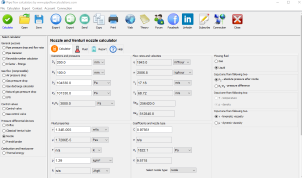
OrificeAirD, d, p1, p2, TQ

Example #7

Task: Calculate flow rate of air through the orifice plate. Orifice internal diameter is 100mm, and tube where orifice is inserted, internal diameter is 200mm. Pressure in front of the orifice is 104000 Pa, and pressure after the orifice is 100000 Pa absolute. Pressures are measured on the corner taps. Temperature of air is 15 C.

Solution: Flow rate is: 1374.5 m3/h
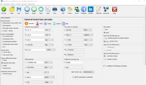
OrificeWaterD, d, p1, p2, TQ

Example #8

Task: Calculate flow rate of water flowing through orifice plate with external diameter of 120 mm and internal diameter of 80 mm. Measured pressures in front and after the orifice is 11000 mm H2O and 10000 mm H2O. Pressure is measured on 1 inch taps.

Solution: Flow rate is: 54.674 m3/h
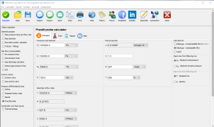
OrificeWaterD, d, p1, p2, TQ

Example #9

Task: Calculate flow rate of water through the orifice with external diameter of 200 mm, internal diameter of 160 mm. Measured pressure drop in front of the orifice is 10729 mm H2O and measured pressure drop is 400 mm H2O. Pressures are measured at corner taps

Solution: Flow rate is: 155.94 m3/h

Related calculators available for download