
🧮 Pipe Network Calculator – Analyze Complex Piping Systems with Ease
🔧 How the Calculation Works — The Node Method
The calculator uses the node method, a well-established engineering approach for solving fluid flow in piping networks:
- Each node in the network must satisfy the mass balance principle: The sum of all flows entering a node equals the sum of all flows leaving it (Σq = 0).
- Unknown node pressures are determined iteratively. Starting from initial estimates, the calculator adjusts flows and pressures until the network satisfies continuity and energy conservation.
- This method is widely used because it is robust, reliable, and scalable for both simple and large systems.
🏗️ Practical Example
Imagine a small network with three pipes meeting at one node. The inlet and outlet pressures are known, but the pressure at the central node is unknown. The calculator applies the node method iteratively to solve for this pressure and the flow in each pipe, ensuring the entire network balances.
✅ Key Benefits
- ⚡ Fast and accurate — saves hours compared to manual iterative calculations.
- 🌐 Supports complex topologies — tanks, pumps, branches, and multiple loops.
- 📊 Instant engineering insights — pressure distribution, flow balance, and head loss per segment.
- 🧩 Great for design and troubleshooting — from HVAC networks to industrial process piping.
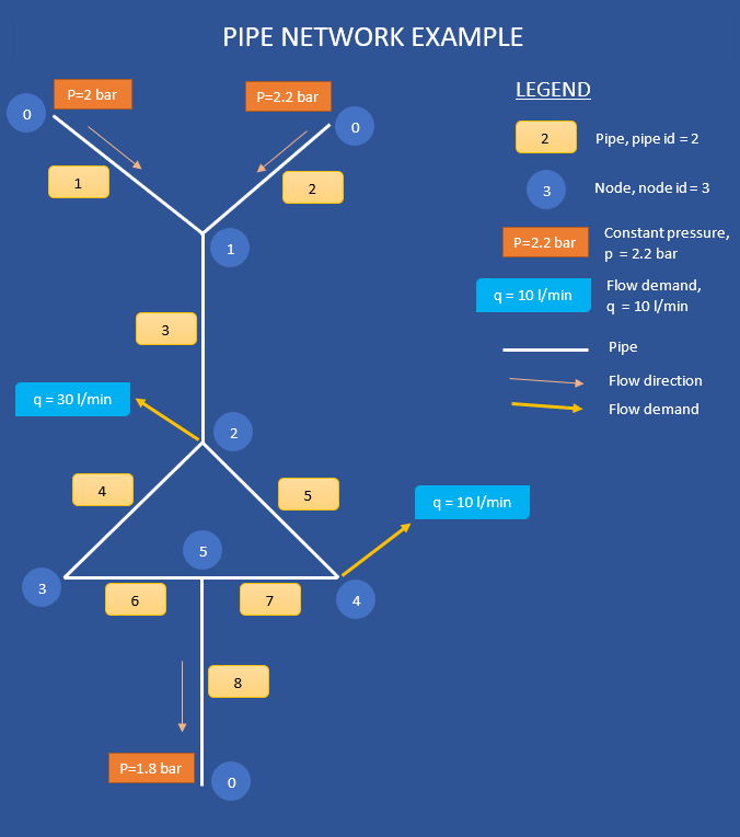
Explanation of network characteristics
- Number of pipes: 8
- Number of nodes: 5
Pipe network is connected in three points to reservoirs with constant pressure. Those three nodes are marked with number 0. Pressures in those three nodes are 2.2 bar, 2.0 bar and 1.8 bar.
Pipe network has two outflow points at nodes 2 and 4. Flows from the network in those two points are 30 l/min and 10 l/min.
This calculation is based on the calculation of pressures in nodes. To initiate calculation, calculator requires to enter some assumptions of the pressure in nodes. I have used values between highest and lowest pressures in points with constant pressure (from 1.95 to 1.91 bar). This is only rough estimate and actual values will be calculated during calculation process.
Download pipe network sketch in .docx format and create your network drawing in a minute.
Download detailed instructions - how to use the calculator
Download
Pipe Network Calculator Instructions - last revision 26th Dec. 2021.
Method of nodes explained and implemented in the online calculator.
Short instructions for creating a network
For the calculation of the pipe network, it is necessary to enter the characteristics of the network which consist of pipes and nodes.
Note: In order to make easier the entry of data on the pipe network, I suggest that you first draw a sketch of the pipe network and mark all the pipes and nodes.
Pipes
For each pipe, it is necessary to enter its ID (integer greater than 0), inner diameter, length, and the roughness of the inner surface. It is also necessary to specify the ID numbers of two nodes that this pipe connects for each pipe. Actual flow direction from one node to another will be calculated and presented after calculation in terms of the arrow pointing from one node ID to another.
Nodes
Nodes are points where two or more pipes join. If the system contains a tank or pump, such places are defined as nodes.
There are two types of nodes.
Fixed pressure nodes - reservoirs and pumps
The first type are nodes where the pressure is constant and in such nodes, the pressure is not calculated - they are e.g. tanks or pumps. For pumps, it is necessary to insert two nodes with constant pressure in front of and behind the pump, and not to insert a pipe between those two nodes. All nodes of this type must be numbered with ID = 0. It is normal to have multiple nodes with ID=0 - like in the system with two or more reservoirs and pumps. This group of nodes are not required to be entered in the table “List of nodes”. Nodes with ID=0 are not possible to enter in the list.
Calculated pressure in nodes - where pipes connect
The second type is nodes in which two or more pipes connect and in which the pressure is the subject of calculation. Optionally, from this type of node, the volume of the flow that flows out of the node can be specified, and this volume is considered constant in the calculation. Normally, the amount of fluid that flows into the node and that flows out of that node is the same. All nodes of the second group must be numbered with an integer greater than 0 (1,2,3,4…).
This group of nodes are required to be entered in the table “List of nodes”.
For all nodes of the second group, it is necessary to enter the assumed pressure values in the node itself. These are the initial values, and the actual values will be displayed after the calculation. It is correct to enter the pressure values that are between the pressures set in the nodes of the first group. For example, if the pipe network between the tank with a constant pressure of 2 bar and the pipe is open to the atmosphere with an overpressure of 0 bar, then it can be assumed that in the nodes in the pipe network the pressures will be from 1.9 bar to 0.1 bar moving from the tank to the pipe that is open atmosphere.